Basic Waveforms and counting
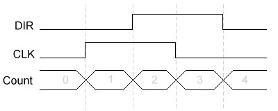
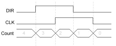
The waveforms for counting are shown below, the clock input is removed for
clarity. DIR and CLK are the inputs from the trackball.
CLK goes high before DIR it is a count up cycle
DIR goes high before CLK it is a count down.
|
Counting UP - CLK leads DIR |
 |
| Counting Down - DIR leads CLK |
 |
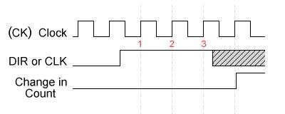
When does counting occur ?
The grey area in the diagram is where CLK or DIR can change but won't effect the current counting action, because internally the current state has already been detected and won't change again for another 3 clocks.
This acts as an effective filter on the inputs, if there is a glitch on DIR or CLK for 1 clock period, or even 2, then it won't effect the counting. The requirement for 3 consistent reads in a row effectively discards any glitches on the input.
| Detecting Change on the DIR or CLK |
 |
The effect of RESOLN on counting
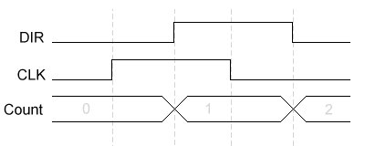
The RESOLN input controls when counters increment or decrement.
| RESOLN | Result |
| 0 | Counting occurs at changes in the state of only the DIR input |
| 1 | Counting occurs at changes in the state of the DIR or CLK input |
When RESOLN = 1 the resolution of the counter is effectively doubled !
| RESOLN = '0' - Counting on changes in DIR only |
 |